What is the OSI Model?
The OSI Model (Open Systems Interconnection Model) is a conceptual framework that defines network communication through seven distinct layers, each playing a specific role in transmitting data across a computer network. Understanding the OSI Model in computer networking is essential for grasping how protocols like TCP/IP, Ethernet, and Internet Protocol (IP) interact to enable seamless end-to-end communication.
In this blog, we’ll break down the seven layers of the OSI Model, starting with a focus on endpoint and network security. First, I’ll explain how the OSI Model’s physical layer is crucial for mitigating rogue devices and preventing unauthorized endpoint access. Ultimately, this forms a key part of a resilient network cybersecurity strategy.
OSI Model Layers
The OSI Model divides network communication into seven layers. Each layer plays an important role in sending data. Understanding these layers helps improve network security. This is especially true for the physical and data link layers, where data is sent in its raw form and vulnerabilities are easiest to exploit.

Physical Layer: The Foundation of Network Communication
The physical layer of the OSI Model is responsible for the transmission and reception of raw data between network devices. Examples of Physical layer devices range from repeaters to hubs. Data units, such as bits, derive from energy in the form of radio waves or electricity. These units are subsequently conveyed through a physical medium, like fiber optic cables or copper wiring. Essentially, this layer manages the physical link connecting a network with its nodes.
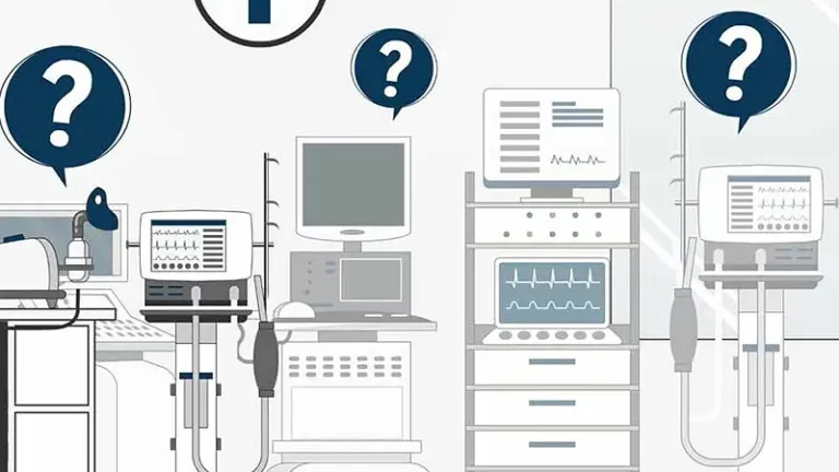
The Physical Layer is key to stopping unauthorized devices from entering the network. Without proper safeguards, rogue devices or network implants can bypass firewalls and go unnoticed. Checking data at this layer helps reduce cyber threats and ensures smooth communication across OSI Model protocols.
Data Link Layer: Managing Local Networks
The OSI model Data Link layer technically consists of two sub-layers. One being Media Access Control (MAC) and the other is Logical Link Control (LLC). This layer is responsible for managing access to the physical layer and facilitating local network communication. Both sub-layers serve as a bridge between Layer 1 (Physical Layer) and Layer 3 (Network Layer), ensuring smooth data transmission.
The MAC layer transports data between itself and Layer 1, while LLC communicates with Layer 3 (LAN – Network Devices). This establishes the data link between the two sub-layers that use switches and bridges.
Network Layer: Routing Data Across Networks
The Network Layer of the OSI Model is responsible for routing data between devices across different networks. This layer includes key components such as routers and IP addresses, which facilitate the efficient movement of network packets.
At this layer, IP protocols like IPv4 and IPv6 determine the optimal routing paths to ensure reliable data transmission across local and wide-area networks (LANs and WANs). By managing packet forwarding, addressing, and traffic control, the Network Layer plays a crucial role in enabling seamless end-to-end communication within the OSI Model.
Transport Layer: Ensuring Reliable Communication
The Transport Layer manages packet sequencing, flow control, and error detection. It ensures data is transmitted reliably. It breaks data into segments and can reorder or resend them if needed.
The protocols used in Layer 4 are Transmission Control Protocol (TCP), and User Datagram Protocol (UDP). Both of these protocols enable different types of data transmission. TCP is known to be a more reliable method, and UDP prioritizes the speed of data transfer.
Session Layer: Managing Communication Channels
The Session Layer of the OSI Model establishes and manages communication channels between devices. It ensures uninterrupted data transfer by overseeing the functionality of active sessions. Layer 5 not only initiates and terminates communication channels but also sets up checkpoints during data transfer, enabling the session to resume if interrupted.
The Session Layer uses different communication modes: namely, simplex, half-duplex, and full-duplex, each of which represents a distinct transmission mode that enables effective data communication.
Presentation Layer: Data Formatting and Encryption
The Presentation Layer of the OSI Model receives data and then prepares it for the Application Layer, making it comprehensible. This process is achieved through several techniques such as compression, encoding, and encryption. As a result, data can be properly received and understood on the opposite end.
Common concepts within layer 6 include known formats such as JPEG, GIF and TIFF.
Application Layer: End-User Interaction
The Application Layer of the OSI Model is the final interface where users interact with computer applications, commonly known as end-user software. This layer supports protocols like File Transfer Protocol (FTP), Hypertext Transfer Protocol (HTTP), and Domain Name System (DNS).
Users interact with end-user software daily, like web browsers and instant messaging. This makes the Application Layer essential for smooth network interaction.
The Physical Layer of the OSI Model
The Physical Layer of the OSI Model primarily handles the physical connection between devices. In particular, it identifies the equipment involved in data transfer. Specifically, Layer 1 defines hardware, cabling, wiring, frequencies, and signals. Moreover, data exists as bits transmitted between nodes.
Existing cybersecurity solutions often overlook physical layer data, providing no data verification at Layer 1. Without this verification, visibility into connected network assets remains uncaptured, leaving the network vulnerable to implants and rogue devices operating on the Physical Layer. Similarly, spoofed peripherals, rogue devices manipulated at the Physical Layer, are falsely identified as legitimate Human Interface Devices (HIDs).
Without physical layer data verification, enterprises risk rogue devices infiltrating their networks and launching harmful hardware attacks. To prevent these attacks at the earliest point, it is crucial to implement robust physical layer security.
Endpoint and Network Security
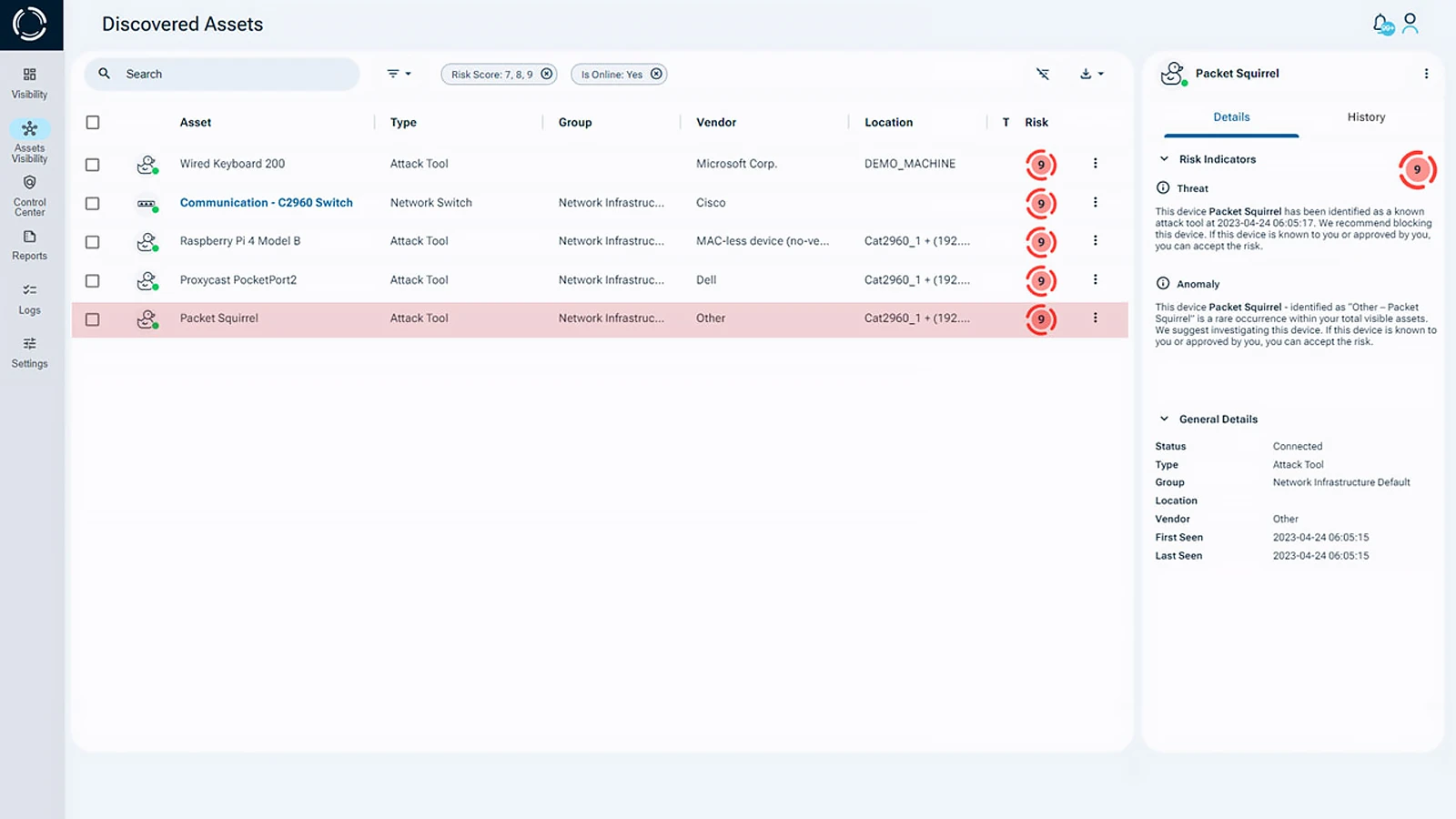
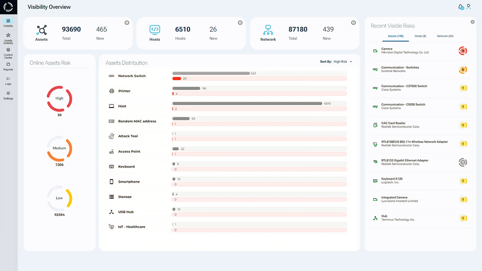
Sepio’s platform uses patented technology designed to improve your organization’s network security. The Physical Layer of the OSI Model is where real data transmission happens in the network infrastructure. By providing advanced visibility and control, Sepio quickly detects and reduces risks to your network. Unlike many other cybersecurity solutions, Sepio focuses on threats at the Physical Layer. This includes network implants, rogue devices, and attacks like spoofed peripherals and harmful USB devices.
What sets Sepio apart is its non-intrusive approach. It does not probe network traffic or use discovery protocols. This means it never monitors proprietary data. As a result, your organization benefits from a simple and efficient implementation process.
Minimize Risks and Strengthen Security with Sepio
Sepio greatly lowers the risk of employee mistakes, strengthening your overall network security. It helps optimize security efforts and reduce costs from breaches. Sepio offers unmatched protection at the Physical Layer of the OSI Model. Take control of both known and hidden assets to prioritize and reduce risks with Sepio’s patented technology.
Talk to an expert. It will help you understand how to use Sepio’s patented technology to gain control of your asset risks.